ESP8266 GPIO control over MQTT using ThingsBoard
- Introduction
- Prerequisites
- List of hardware and pinouts
- Wiring schemes
- ThingsBoard configuration
- Programming the ESP8266
- Autonomous operation
- Troubleshooting
- Data visualization
- See also
- Your feedback
- Next steps
Introduction
ThingsBoard is an open-source server-side platform that allows you to monitor and control IoT devices. It is free for both personal and commercial usage and you can deploy it anywhere. If this is your first experience with the platform we recommend to review what-is-thingsboard page and getting-started guide.
This sample application will allow you to control GPIO of your ESP8266 device using ThingsBoard web UI. We will observe GPIO control using LEDs connected to the pins. The purpose of this application is to demonstrate ThingsBoard RPC capabilities.
The application that is running on ESP8266 is written using Arduino SDK which is quite simple and easy to understand. ESP8266 offers a complete and self-contained Wi-Fi networking solution. ESP8266 pushes data to ThingsBoard server via MQTT protocol by using PubSubClient library for Arduino. Current GPIO state and GPIO control widget is visualized using built-in customizable dashboard.
The video below demonstrates the final result of this tutorial.
Prerequisites
You will need to have ThingsBoard server up and running. Use either Live Demo or Installation Guide to install ThingsBoard.
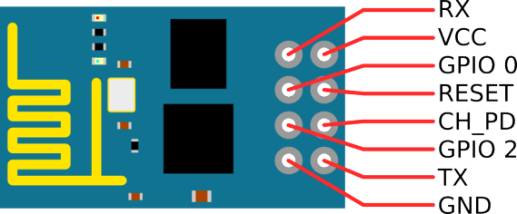
List of hardware and pinouts
-
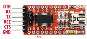
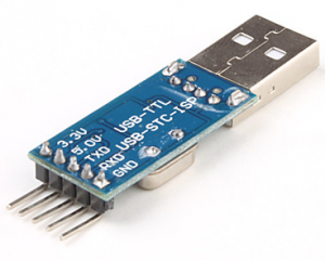
USB to TTL
-
Breadboard
-
2 female-to-female jumper wires
-
7 female-to-male jumper wires
-
2 LEDs
-
3.3V power source (for example 2 AA batteries)
Wiring schemes
Programming/flashing scheme
| ESP8266 Pin | USB-TTL Pin |
|---|---|
| ESP8266 VCC | USB-TTL VCC +3.3V |
| ESP8266 CH_PD | USB-TTL VCC +3.3V |
| ESP8266 GND (-) | USB-TTL GND |
| ESP8266 GPIO 0 | USB-TTL GND |
| ESP8266 RX | USB-TTL TX |
| ESP8266 TX | USB-TTL RX |
| LED 1 Pin | USB-TTL Pin |
|---|---|
| cathode | USB-TTL GND |
| LED 1 Pin | ESP8266 Pin |
|---|---|
| anode | ESP8266 GPIO 2 |
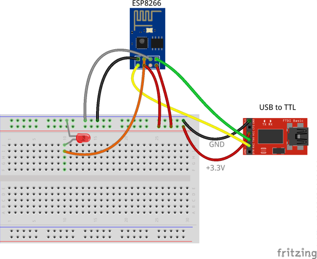
The following picture summarizes the connections for this project in programming/debug mode:
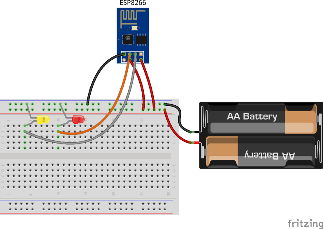
Final schema (Battery Powered)
| ESP8266 Pin | 3.3V power source |
|---|---|
| ESP8266 VCC | VCC+ |
| ESP8266 CH_PD | VCC+ |
| ESP8266 GND (-) | VCC- |
| LED 1 Pin | ESP8266 Pin |
|---|---|
| anode | ESP8266 GPIO 2 |
| LED 1 Pin | 3.3V power source |
|---|---|
| cathode | VCC- |
| LED 2 Pin | ESP8266 Pin |
|---|---|
| anode | ESP8266 GPIO 0 |
| LED 2 Pin | 3.3V power source |
|---|---|
| cathode | VCC- |
The final picture:
ThingsBoard configuration
Note ThingsBoard configuration steps are necessary only in case of local ThingsBoard installation. If you are using Live Demo instance all entities are pre-configured for your demo account. However, we recommend reviewing this steps because you will still need to get device access token to send requests to ThingsBoard.
Provision your device
This step contains instructions that are necessary to connect your device to ThingsBoard.
Open ThingsBoard Web UI (http://localhost:8080) in browser and login as tenant administrator
- login: tenant@thingsboard.org
- password: tenant
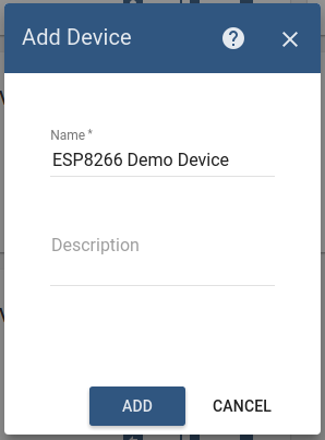
Go to “Devices” section. Click “+” button and create a device with the name “ESP8266 Demo Device”.
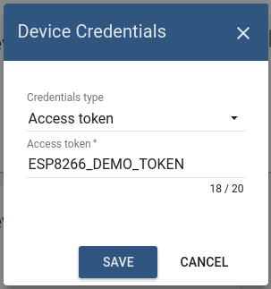
Once device created, open its details and click “Manage credentials”. Copy auto-generated access token from the “Access token” field. Please save this device token. It will be referred to later as $ACCESS_TOKEN.
Click “Copy Device ID” in device details to copy your device id to the clipboard. Paste your device id to some place, this value will be used in further steps.
Provision your dashboard
Download the dashboard file using this link. Use import/export instructions to import the dashboard to your ThingsBoard instance.
Programming the ESP8266
Step 1. ESP8266 and Arduino IDE setup.
In order to start programming ESP8266 device, you will need Arduino IDE installed and all related software.
Download and install Arduino IDE.
After starting Arduino IDE, open the preferences from the ‘file’ menu.
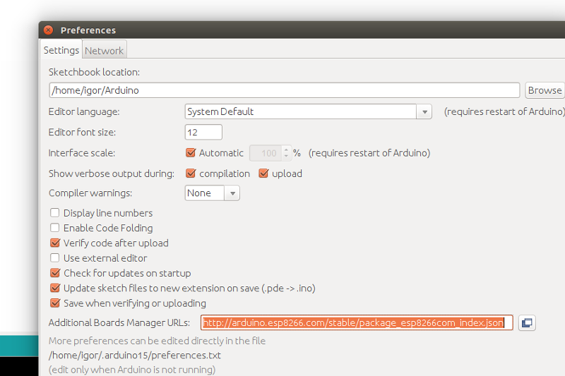
Paste the following URL to the “Additional board managers URL”: http://arduino.esp8266.com/stable/package_esp8266com_index.json
Close the screen by clicking the OK button.
Now we can add the board ESP8266 using the board manager.
In the menu tools, click on the menu option Board: “Most likely Arduino UNO”. There you will find the first option “Board Manager”.
Type in the search bar the 3 letters ESP. Locate and click on “esp8266 by ESP8266 Community”. Click on install and wait for a minute to download the board.
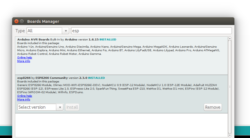
Note that this tutorial was tested with the “esp8266 by ESP8266 Community” version 2.3.0.
In the menu Tools “Board “Most likely Arduino UNO” three new boards are added.
Select “Generic ESP8266 Module”.
Prepare your hardware according to the Programming/flashing scheme. Connect USB-TTL adapter with PC.
In the menu Tools, select the corresponding port of the USB-TTL adapter. Open the serial monitor (by pressing CTRL-Shift-M or from the menu Tools). Set the key emulation to “Both NL & CR” and the speed to 115200 baud. This can be set at the bottom of the terminal screen.
Step 2. Install Arduino libraries.
Open Arduino IDE and go to Sketch -> Include Library -> Manage Libraries. Find and install the following libraries:
Note that this tutorial was tested with the following versions of the libraries:
- PubSubClient 2.6
- ArduinoJson 5.8.0
Step 3. Prepare and upload a sketch.
Download and open esp8266-gpio-control.ino sketch.
Note You need to edit following constants and variables in the sketch:
- WIFI_AP - name of your access point
- WIFI_PASSWORD - access point password
- TOKEN - the $ACCESS_TOKEN from ThingsBoard configuration step.
- thingsboardServer - ThingsBoard HOST/IP address that is accessible from within your wifi network. Specify “demo.thingsboard.io” if you are using live demo server.
resources/esp8266-gpio-control.ino |
|---|
|
Connect USB-TTL adapter to PC and select the corresponding port in Arduino IDE. Compile and Upload your sketch to the device using “Upload” button.
After the application is uploaded and started it will try to connect to ThingsBoard node using mqtt client and upload current GPIOs state.
Autonomous operation
When you have uploaded the sketch, you may remove all the wires required for uploading including USB-TTL adapter and connect your ESP8266 and LEDs directly to the power source according to the Final wiring schema.
Troubleshooting
In order to perform troubleshooting, you should assemble your hardware according to the Programming/flashing scheme. Then connect USB-TTL adapter with PC and select port of the USB-TTL adapter in Arduino IDE. Finally, open “Serial Monitor” in order to view the debug information produced by serial output.
Data visualization
Finally, open ThingsBoard Web UI. You can access this dashboard by logging in as a tenant administrator.
In case of local installation:
- login: tenant@thingsboard.org
- password: tenant
In case of live-demo server:
- login: your live-demo username (email)
- password: your live-demo password
See live-demo page for more details how to get your account.
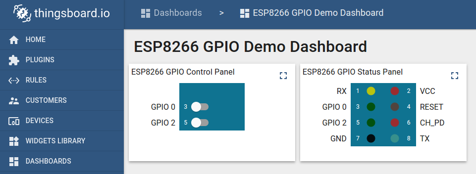
Once logged in, open Dashboards->ESP8266 GPIO Demo Dashboard page. You should observe demo dashboard with GPIO control and status panel for your device. Now you can switch status of GPIOs using control panel. As a result, you will see LEDs status change on the device and on the status panel.
Below is the screenshot of the “ESP8266 GPIO Demo Dashboard”.
See also
Browse other samples or explore guides related to main ThingsBoard features:
- Device attributes - how to use device attributes.
- Telemetry data collection - how to collect telemetry data.
- Using RPC capabilities - how to send commands to/from devices.
- Rule Engine - how to use rule engine to analyze data from devices.
- Data Visualization - how to visualize collected data.
Your feedback
Don’t hesitate to star ThingsBoard on github to help us spread the word. If you have any questions about this sample - post it on the issues.
Next steps
-
Getting started guides - These guides provide quick overview of main ThingsBoard features. Designed to be completed in 15-30 minutes.
-
Installation guides - Learn how to setup ThingsBoard on various available operating systems.
-
Connect your device - Learn how to connect devices based on your connectivity technology or solution.
-
Data visualization - These guides contain instructions how to configure complex ThingsBoard dashboards.
-
Data processing & actions - Learn how to use ThingsBoard Rule Engine.
-
IoT Data analytics - Learn how to use rule engine to perform basic analytics tasks.
-
Advanced features - Learn about advanced ThingsBoard features.
-
Contribution and Development - Learn about contribution and development in ThingsBoard.